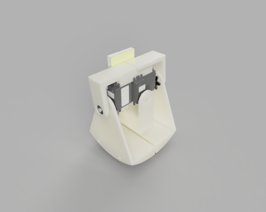
The walking version of the Egg Robot walked last week. Unfortunately, it also distorted its legs so that it drags the raised foot on each step, disrupting its path. To fix this, I added a brace to support the legs from the outside.

In the previous design, the entire weight of the robot was resting on the connection between the servo horn and the servo. The servo horn appears to have deformed. The deformation causes the two feet to press together, sliding the unweighted leg downward. The unweighted leg scrapes against the ground when taking a step, disrupting the path of the robot. I added a U-shaped brace that supports the outside of the legs using shafts built into leg pressed into bearings mounted on the brace.
In other updates, I added a serial communication and control with the robot. Now I can manually set the servo positions and command actions from the serial command line. I borrowed some standard serial handling and parsing code from the Arduino Forums and modified it to read servo control commands.
Next Week’s Work
- Check fit of bearings and update model with clearances
- Print the new version 5
- Assemble new version 5
- Test for dragging foot
Bonus Work
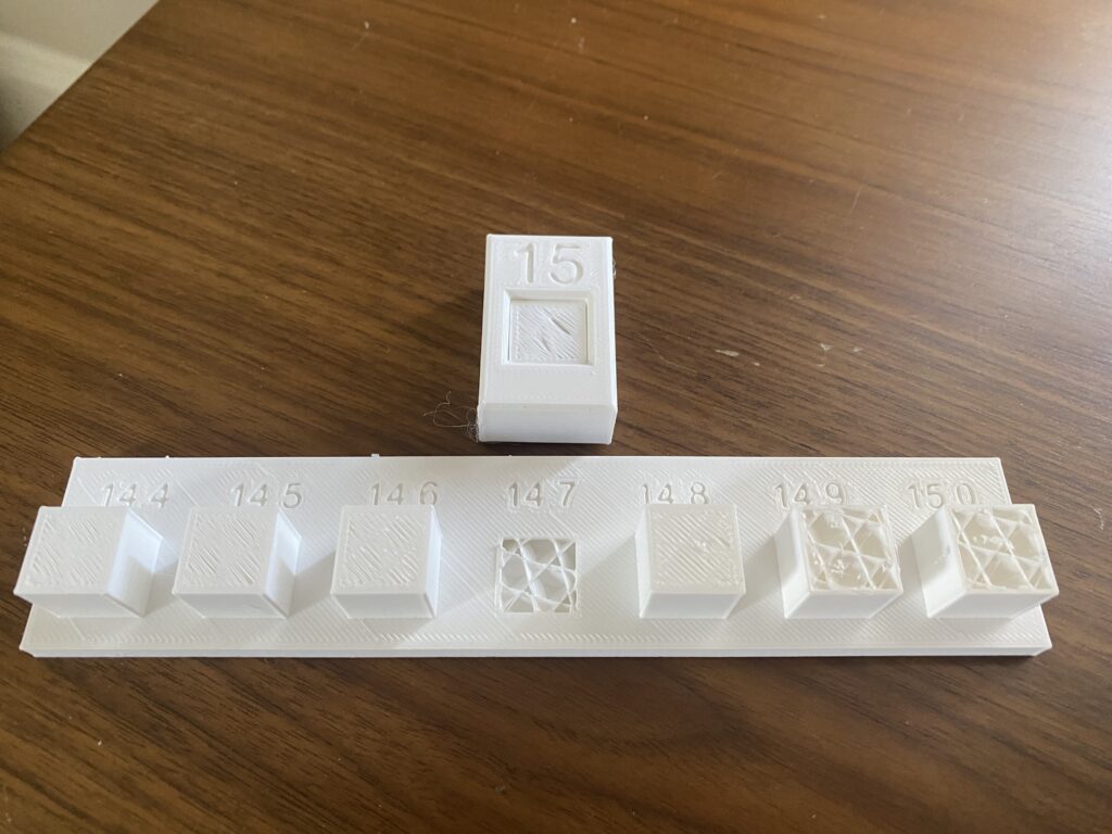
Learned about different types of fits: interference, transitional, and clearance. To learn about the clearances required for different fits on my 3D printer, I designed and printed a small test fixture where a fixed 15.0 mm square hole is mated with shafts of various sizes between 14.4, 14.5, …, 15.0 mm. The results: 14.5 mm provided a clearance fit, 14.6 provided a transitional fit that could be separated by hand, and 14.7 mm provided a clearance fit that I couldn’t separate without breaking the fixture.

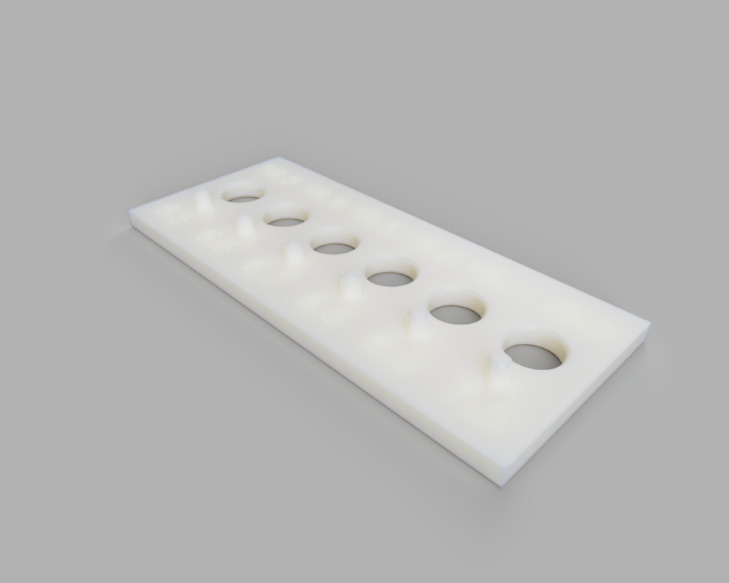
In a similar path, I designed a fit tests fixture for the bearings that I chose for the leg support described above. I ran out of filament, but I will test the fixture first thing next week when new filament and the bearings arrive.

